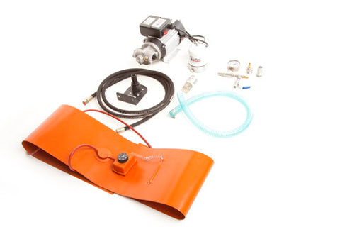
Centrifuge Kit Assembly - Size 20
A quick guide to assembling the Scintex centrifuge kits using the size 20 centrifuge. This will directly apply to models SOC020P & SOC020PH. The larger Size 60 centrifuge kits are near identical with a few slight differences in the size of the fittings used. These centrifuge kits are ideal for filtering and polishing many types of fuels such as diesel, biodiesel, motor oils, engine oils and vegetable oils to name a few.
Note: We have a video of the centrifuge kit operating on Youtube and you will visually be able to see how the system plumbs together. Please view this before attempting installation and assembly.
STEP 1: For centrifuge kits with the optional drum band heater ONLY
The band heater is designed for use with drums close to the size of a standard 44 Gallon drum. Install by wrapping the heater around the drum and connecting the springs included to keep the band taught around the drum.
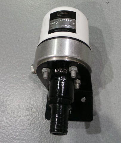
STEP 2: Mounting the centrifuge
Select a mounting location, keeping in mind that the hoses must reach the drum and pump as well as be close to a power supply for the pump. Mount the centrifuge bracket using the mounting bolt holes. Scintex advises mounting the centrifuge bracket over the collection drum so the filtered liquid is easily collected. Note: There is almost no fluid pressure on the outlet side of the centrifuge and the filtered liquid will need to gravity feed away. Mount the centrifuge to the bracket using the 4 bolts, nuts and washers supplied. Don't forget to put the gasket between the centrifuge outlet and the mounting bracket.

STEP 3: Suction hose & inlet strainer
Thread tape the inlet strainer / foot valve and attach the 1” nylon hose tail. Attach suction hose to 1” hose tail with foot valve and secure with hose clamp. Place the second hose clamp over the suction hose with the foot valve and then attach the second 1” nylon hose tail to the opposing end of hose and secure with clamp. The inlet strainer will prevent large particulate matter from blocking the pump or the jets on the centrifuge. The inbuilt one way valve will assist in pump priming.

Note: Remember to apply thread tape to all fittings as pictured.
STEP 4: Discharge Hose
Attach the reducing fittings together 1”-3/8” using thread tape between each and attach the ball valve. Connect the centrifuge hose to the ball valve using 3/8” hex nipple (remember to use thread tape). This is high pressure, non flex hose designed specifically for use with centrifuge and other high pressure applications.

STEP 5: Attach pressure gauge to centrifuge
Attach a 1/4”-3/8” reducer (thread tape) to pressure gauge and attach to centrifuge. This is the inlet side of the centrifuge.

STEP 6: Attach suction hose and discharge hose (including bypass valve) to the pump

STEP 7: Connect centrifuge to the 3/8" discharge line

Brief guide to centrifuge operation:
The gear pump supplied with this kit pumps at 9LPM which is more flow than the size 20 centrifuge can handle. This is why a bypass valve is incorporated. The bypass valve also allows you to vary the pressure applied to the centrifuge. Always start the pump with the bypass valve completely open so all fluid is bypassing the centrifuge. You should have a 0 PSI reading on the pressure gauge. Start by slowly closing the valve to direct flow and pressure to the centrifuge. Increase the pressure in a continuous manner until the pressure gauge is reading 70 PSI to 100 PSI. The optimum operating pressure is 100 PSI, however, we don't advise going any higher than this. If only 70 PSI can be reached with the valve completely closed this is fine and will still provide a good filtration. The centrifuge can be used as a single pass filter or you can set up to recirculate the fuel as shown in our demonstration video here: