

Engine Fuel Flow Pulse Meter – 0.5 to 10,000 LPH
Description
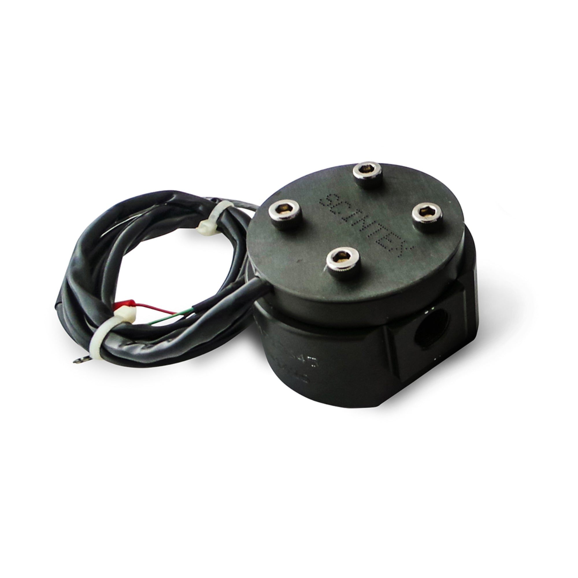
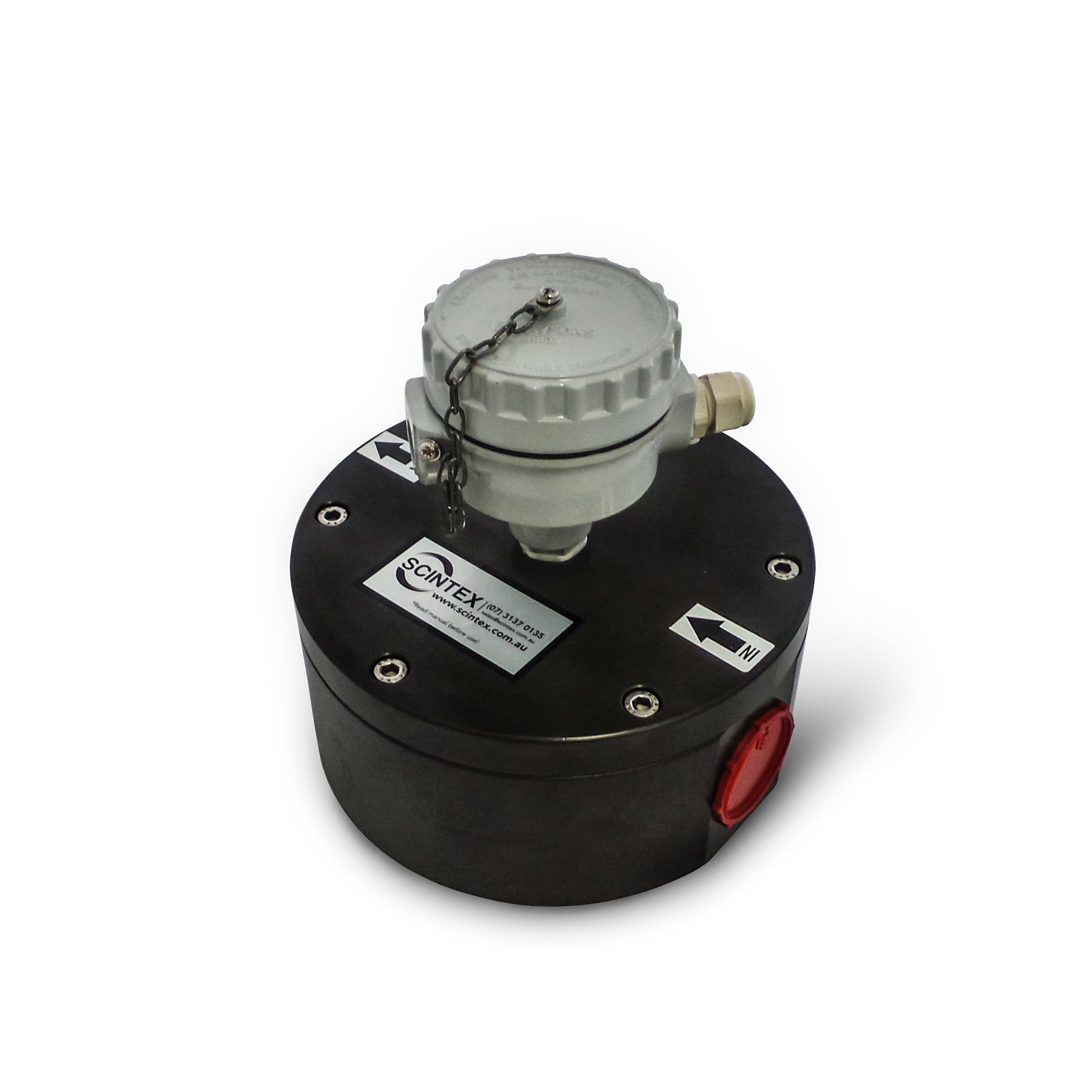
Measure fuel flow through engine, vehicle and equipment fuel systems with these in-line pulse fuel flow meters. Available in multiple sizes covering flow ranges from 0.5 LPH through to 10,000 LPH, each meter generates an electronic pulse output for connection to compatible monitoring, logging or control equipment.
The positive-displacement gear design uses a Hall-effect sensor to detect rotation and generate the pulse signal. BSP female threaded ports make it possible to adapt the meter to a range of compatible fuel hose and pipe installations.
Engine Fuel Flow Pulse Meter
These compact fuel flow meters are designed for measuring liquid fuel flow in engines, vehicles, generators, machinery and other compatible fuel systems.
As fuel passes through the meter, the internal gears rotate. A magnet incorporated into the measuring mechanism activates a Hall-effect sensor, producing an NPN open-collector pulse output.
This pulse signal can then be used by compatible displays, counters, data loggers, monitoring systems or other electronic equipment to calculate fuel flow and consumption.
Fuel Flow Meter Features
- Flow ranges from 0.5 to 10,000 LPH
- Multiple meter sizes available
- Positive-displacement gear measuring principle
- Hall-effect pulse sensor
- NPN open-collector output
- 3–24V DC supply voltage
- Stated accuracy of ±1% RS in the standard installation position
- Individual calibration pulse count supplied with each meter
- Low stated pressure drop
- BSP female inlet and outlet connections
- Anodised aluminium rotor and casing
- Stainless steel shaft
- NBR O-ring
- Serviceable internal gear arrangement
- 12 month warranty
Wide Range of Fuel Flow Rates
Six meter sizes are available, allowing the sensor to be selected according to the expected fuel flow of the application.
| Flow Range | Inlet / Outlet |
|---|---|
| 0.5–60 LPH | 1/4" BSP Female |
| 5–150 LPH | 1/4" BSP Female |
| 20–300 LPH | 3/8" BSP Female |
| 50–800 LPH | 1/2" BSP Female |
| 200–4,000 LPH | 1" BSP Female |
| 500–10,000 LPH | 1-1/2" BSP Female |
Selecting the Correct Flow Meter
Select a meter with an operating range appropriate for the expected fuel flow through that section of the system. For best measurement performance, the normal operating flow should remain within the specified range of the selected meter.
The BSP female connections allow suitable hose tails, threaded adaptors and other fittings to be selected according to the fuel line being used.
Pulse Output for Fuel Monitoring
The flow meter operates from a 3–24V DC electrical supply and provides an NPN open-collector pulse output.
The supplied nominal pulse specification is approximately 0.661mL per pulse / 1513 pulses per litre. Each meter is individually calibrated and supplied with its applicable pulse count per litre, which should be used when configuring the connected monitoring or data-logging equipment.
This product is a pulse-output flow sensor and does not by itself provide a fuel consumption display. A compatible display, controller, counter or data acquisition system is required where a visual reading or calculated fuel consumption is needed.
Fuel Consumption Applications
These meters can be incorporated into fuel monitoring systems for a wide range of engine and equipment applications, including:
- Trucks and commercial vehicles
- Cars and 4WDs
- Tractors and agricultural machinery
- Excavators, loaders, dozers and graders
- Forklifts and cranes
- Generators and lighting towers
- Construction and earthmoving equipment
- Mining and industrial machinery
- Marine engines and vessels
- Fixed engine installations
Compatible Fluids
The supplied compatibility information includes:
- Diesel
- Biodiesel
- Unleaded petrol / gasoline
- Kerosene
- Light oil
- Heavy oil
Fluid viscosity, temperature and material compatibility can affect meter performance. Confirm suitability of the anodised aluminium, stainless steel and NBR wetted components for unusual fuels, blends or operating conditions.
Serviceable Gear Design
The meter uses an internal gear measuring mechanism rather than a plastic paddle-style flow sensor. The rotor and casing are specified as anodised aluminium with a stainless steel shaft and NBR sealing.
The internal measuring components can be accessed for inspection and cleaning if contamination causes the gears to become restricted.
Fuel Flow Meter Specifications
| Specification | Details |
|---|---|
| Meter Type | Positive-displacement gear pulse flow meter |
| Available Flow Ranges | 0.5–60 / 5–150 / 20–300 / 50–800 / 200–4,000 / 500–10,000 LPH |
| Accuracy | ±1% RS – standard installation position |
| Stated Pressure Drop | Approx. 2.5kPa / 0.36 PSI at 100% of stated flow range |
| Fluid & Ambient Temperature | -40°C to +80°C |
| Nominal Pulse Unit | Approx. 0.661mL/pulse |
| Nominal Pulse Rate | Approx. 1513 pulses/L – individual calibration value supplied |
| Supply Voltage | 3–24V DC |
| Output Signal | NPN open collector |
| Rotor & Casing | Anodised aluminium |
| Shaft | Stainless steel |
| O-Ring | NBR |
| Stated Compatible Fluids | Kerosene, petrol/gasoline, diesel, biodiesel, light oil and heavy oil |
| Dimensions | Varies by model – starting from approx. 65 × 60 × 40mm |
| Weight | Varies by model – starting from approx. 320g |
| Certification | CE certificate and calibration certificate available on request at additional charge |
| Warranty | 12 months |
Fuel Filtration is Important
Install the flow meter downstream of an appropriate fuel filter.
A filter of 50 micron or finer is recommended in the supplied installation information to help prevent rust, scale and other tank contamination from entering and restricting the meter's internal gears.
Regularly inspect and service the upstream filter, particularly where fuel is being drawn from older tanks or installations where contamination may be present.
Installation Considerations
The meter is installed in-line with the fuel system using suitable BSP threaded fittings. Ensure all hose, fittings, seals and other components are compatible with the fuel and operating conditions.
Electrical installation requires connection of the sensor supply and pulse-output wiring to compatible monitoring equipment. The connected equipment must be configured using the calibration information supplied with the individual meter.
For engine fuel-consumption measurement, consider the complete fuel system design. Engines with a fuel return line may require measurement of both supply and return flow, with the difference between the two flows used to determine actual engine consumption.
Installation should not introduce excessive restriction, leakage or air ingress into the engine fuel system.