

Digital Fuel Consumption Calculator & Flow Display – Dual Pulse Input, RS-485 & USB
Description
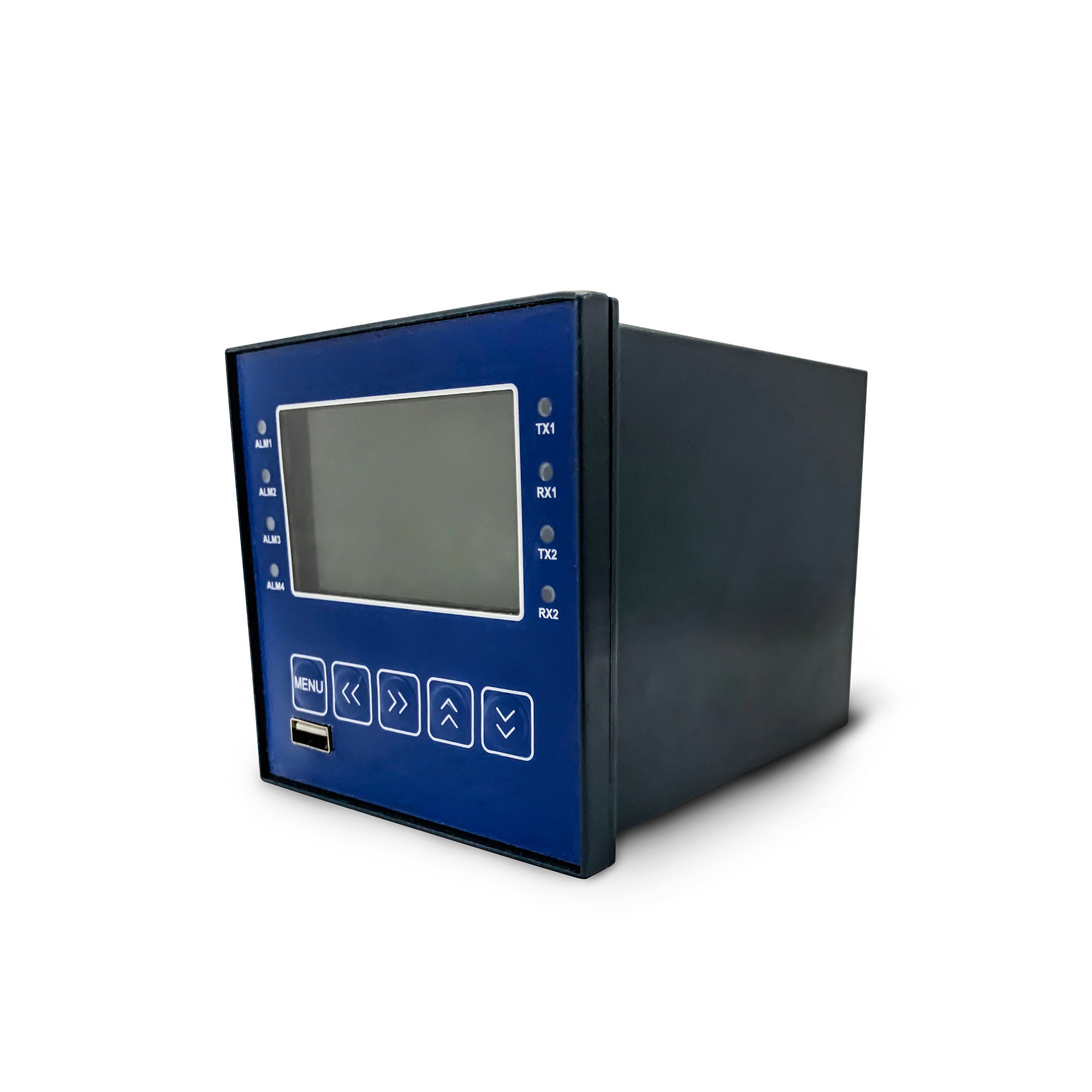
The Digital Fuel Consumption Calculator & Flow Display is designed for engines and fuel systems that use separate supply and return fuel lines. By accepting pulse signals from up to two compatible flow meters, the unit can monitor supply flow, return flow and calculate net fuel consumption.
The display can also record operating data internally and provide data output through RS-485 and USB interfaces for connection to compatible logging or control systems.
Digital Fuel Consumption Calculator & Flow Display
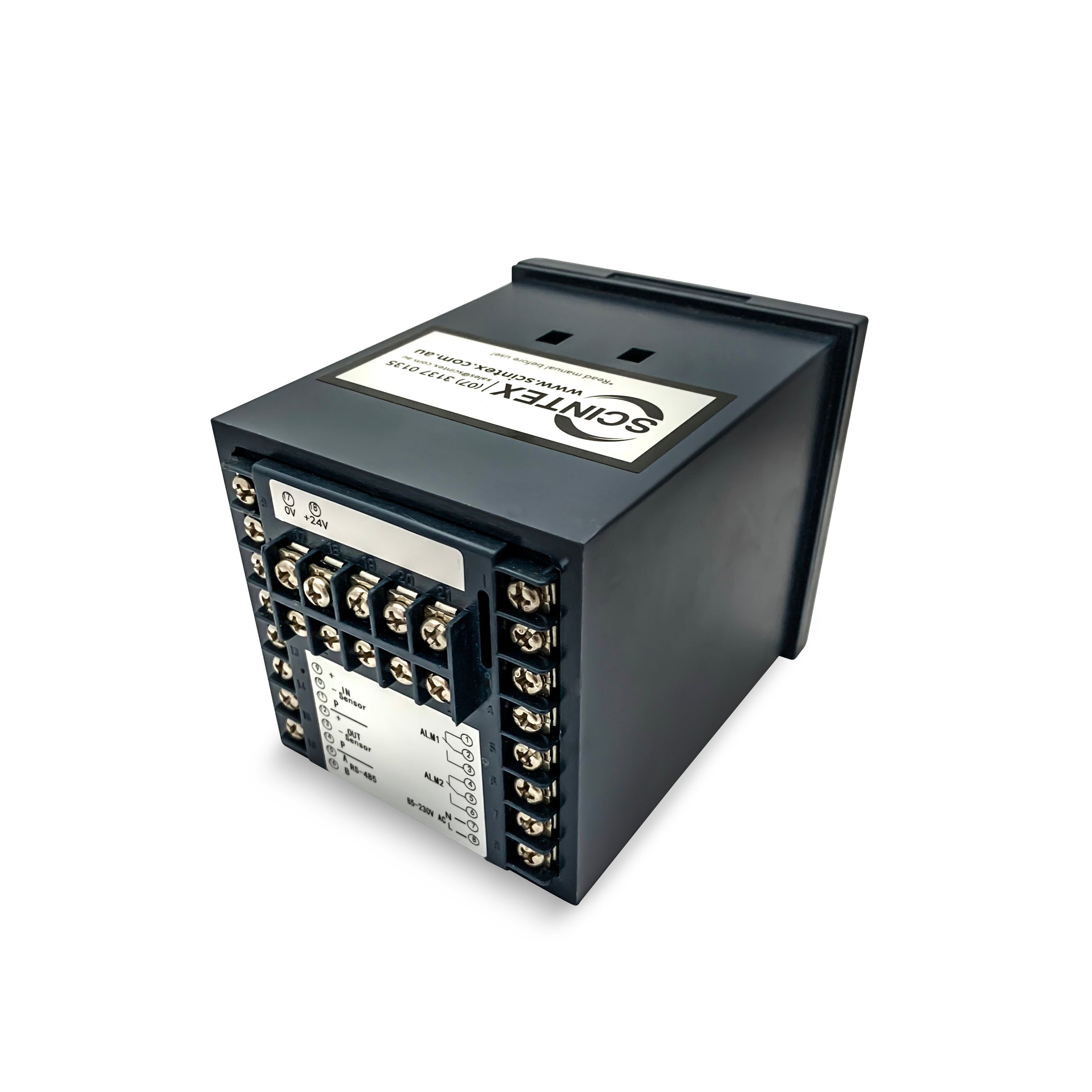
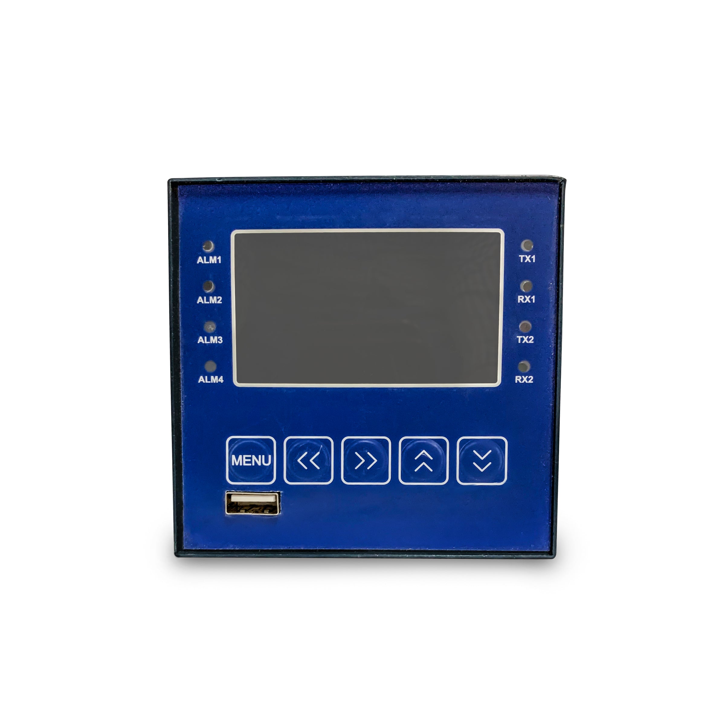
This low-voltage digital display accepts two pulse flow meter inputs, allowing fuel flow in supply and return lines to be monitored simultaneously.
For diesel engines with return fuel systems, net fuel consumption can be calculated from the difference between the supply and return flow measurements.
- Connect up to 2 compatible pulse-output flow meters
- Monitor supply and return fuel flow
- Calculate net fuel consumption
- Displays instantaneous flow in LPH, LPM, GPH or GPM
- Totalises supply, return and calculated consumption
- Monitors flow time for supply and return channels
- 3 levels of password-protected access
- 9–36V DC or 240V AC power options
- RS-485 data output
- USB interface
- Internal data logging with date and time
- Backlit LCD display
Supply, Return & Net Fuel Consumption
Many diesel engines circulate more fuel through the supply line than the engine actually consumes, with unused fuel returning to the tank.
When suitable pulse flow meters are installed in both the supply and return lines, this display can monitor both flow rates and calculate the difference as net fuel consumption.
The accuracy of the complete fuel consumption system will depend on the accuracy, calibration, installation and suitability of the connected flow meters as well as the display configuration.
Digital Flow Monitoring
The display can show instantaneous flow rates in multiple units and maintain separate totals for:
- Supply flow
- Return flow
- Calculated consumed flow
This makes the unit suitable for fuel-use monitoring, testing, servicing and operational record keeping where compatible flow meters are installed.
Internal Data Logging
The unit includes internal memory for data logging with date and time information. Stored information can be reviewed on the display or extracted through the USB interface.
For installations requiring integration with external logging or control systems, the RS-485 output provides an additional communication option.
View RS-485 / Modbus Communication Information
Typical Applications
- Diesel engine fuel consumption monitoring
- Generators and power equipment
- Construction and earthmoving equipment
- Agricultural machinery
- Marine engines
- Industrial equipment
- Fuel and oil flow monitoring with suitable pulse meters
- Fixed and mobile machinery
The unit may also be used with petrol or oil systems where the connected pulse flow meters and all wetted components are suitable for the fluid and application.
Installation Environment
Important: The display unit does not have a stated IP rating and should be installed inside a suitable enclosure where protection from water, dust and environmental exposure is required.
For marine or corrosive environments, the installation must provide suitable protection against moisture and corrosion.
Digital Display Specifications
| Specification | Details |
|---|---|
| Power Supply | 9–36V DC / 240V AC |
| Display | 128 x 64 backlit LCD |
| Flow Rate Display Range | -9999 to 9999 |
| Flow Total Range | 0 to 999999.99 |
| Display Accuracy | 0.2% FS ±1 digit |
| Operating Temperature | -20°C to 60°C |
| Power Consumption | <10W |
| Inputs | 2 x pulse inputs |
| Outputs / Interfaces | RS-485 / USB |
| Face Plate Dimensions | 96 x 96mm |
| Password Protection | 3 access levels |
| Internal Data Logging | Included |
| Protection Functions | Low-voltage, short-circuit and thermal protection |
| Warranty | 12 Months |
Note: External pulse flow meters are required for flow measurement and must be selected to suit the fluid, flow range, pressure, temperature and installation. Overall system accuracy is dependent on both the display and the connected flow meters.