

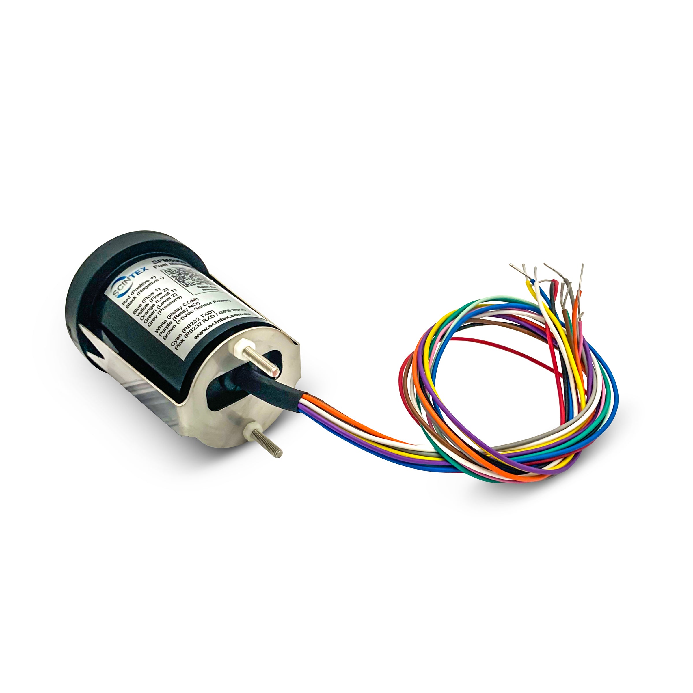
Engine Fuel Consumption Gauge Kit (Supply & Return Lines)
Description
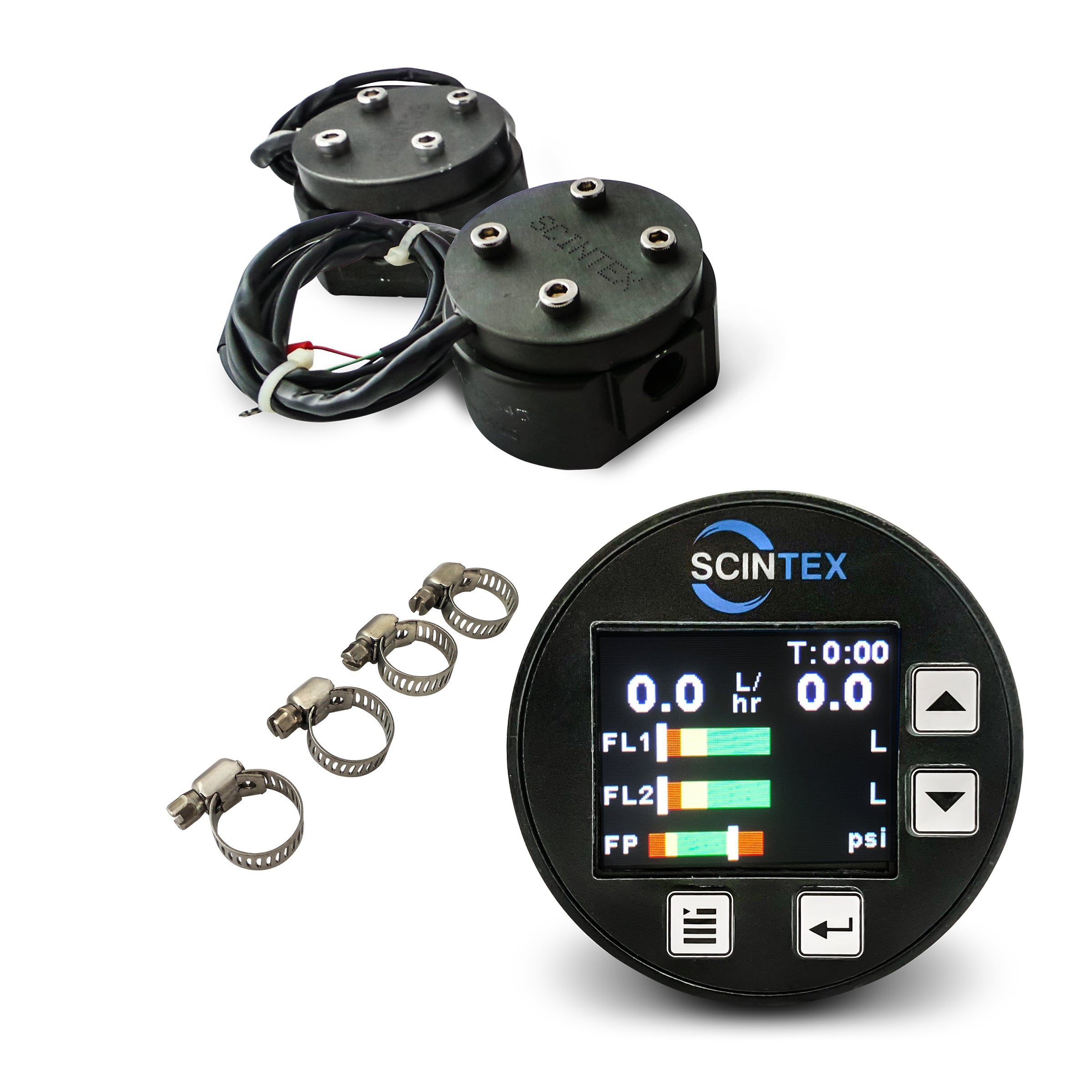
The Engine Fuel Consumption Gauge Kit provides accurate fuel usage monitoring for engines with supply and return fuel lines. The complete system uses two inline precision flow meters together with a digital colour display to measure fuel supplied to the engine, fuel returned to the tank and the actual fuel consumed.
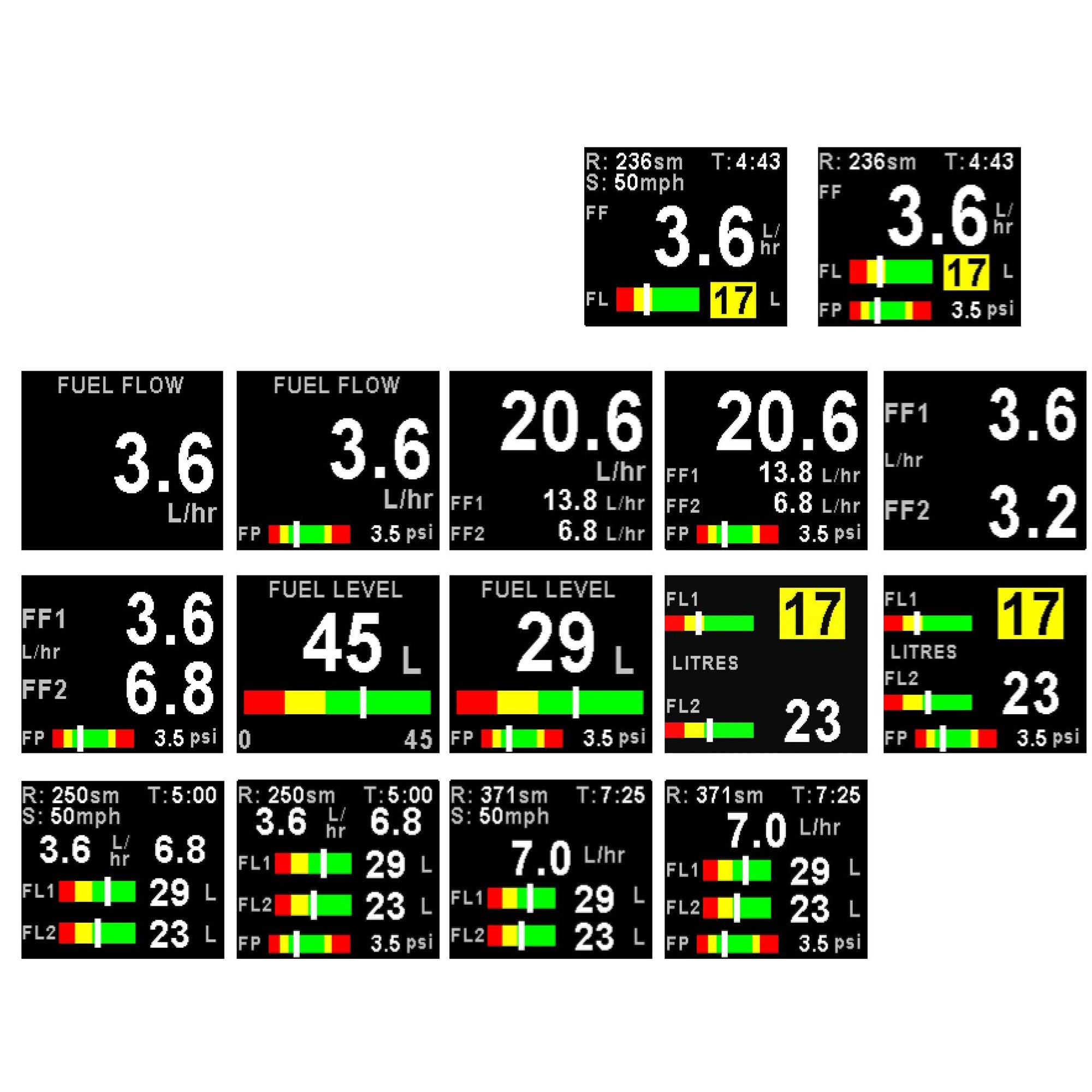
Ideal for diesel engines in boats, yachts, generators, tractors, farm machinery, trucks and other vehicles, the system can display real-time consumption in litres per hour and supports additional functions including fuel remaining, range calculations, fuel pressure and NMEA integration.
Engine Fuel Flow & Consumption Gauge Kit
- Measures actual engine fuel consumption using supply and return flow meters
- Displays fuel consumption in litres per hour and other selectable units
- Suitable for diesel, petrol, biodiesel and other compatible fuels
- Precision gear-type inline flow meters
- Supports one or two fuel flow senders
- Supports one or two fuel tanks
- Can display fuel remaining when connected to compatible tank senders
- Manual tank volume entry available where no level sender is fitted
- Multi-point calibration for irregular-shaped tanks
- Supports NMEA-enabled RS232 GPS input for range calculations
- Can export compatible data to NMEA 2000 marine systems
- Password protection for settings and totaliser functions
- 12V-36V display power supply
- Wide range of flow meter sizes available
Measure Actual Fuel Consumption
Many diesel engines circulate substantially more fuel through the engine than they actually consume. Fuel is supplied from the tank to the engine, with unused fuel then returned to the tank.
For these systems, measuring only the supply line will not provide an accurate indication of fuel consumption.
The dual flow meter kit measures both:
- Fuel supplied to the engine
- Fuel returned to the tank
The display calculates the difference between these two flow rates to determine the engine's actual fuel consumption.
For example, if 100 L/hr is being supplied to the engine and 70 L/hr is returning to the tank, actual engine consumption is approximately 30 L/hr.
Monitor Fuel Economy in Real Time
Real-time fuel consumption data can help operators understand how engine speed, load and operating conditions affect fuel usage.
This is particularly useful in marine, agricultural and generator applications where relatively small changes in RPM or load can result in meaningful changes in fuel consumption over long operating periods.
The display allows the operator to compare fuel usage at different operating conditions and make informed decisions about the most efficient operating point.
Fuel Remaining & Tank Level Monitoring
The display can monitor fuel remaining in up to two tanks when connected to compatible fuel level sender units.
For irregularly shaped tanks, a multi-point calibration system with up to six calibration points can be used to improve the accuracy of the displayed tank level.
If no fuel level sender is installed, the user can manually enter the tank volume and allow the display to estimate remaining fuel based on recorded consumption.
Range Calculations
The system can estimate remaining travel range based on fuel consumption and available fuel.
Users can manually enter cruising speed, allowing the display to calculate estimated range using current consumption and remaining fuel.
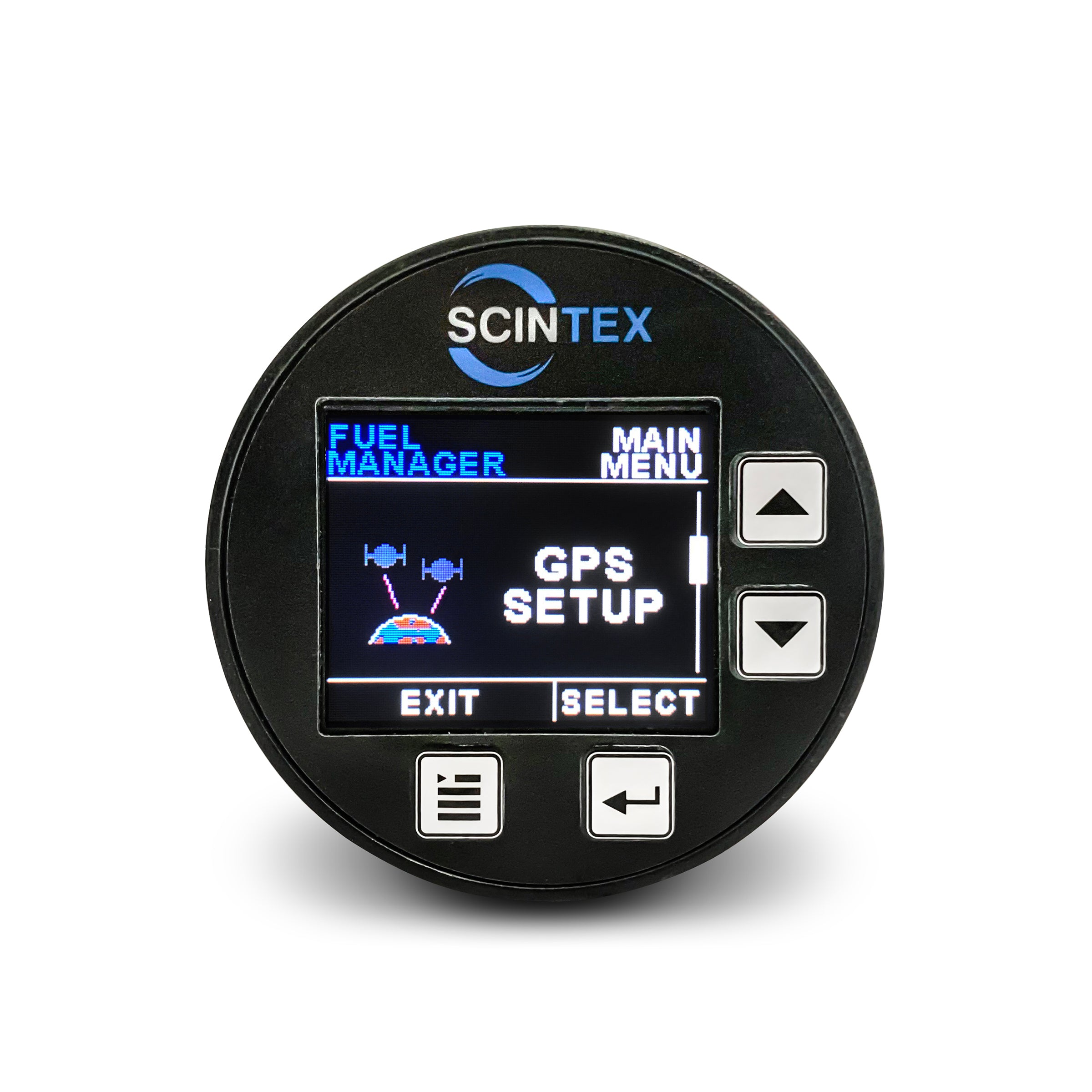
For more automated operation, a compatible NMEA-enabled RS232 GPS receiver can be connected so the system can use vehicle or vessel speed data when calculating range.
NMEA 2000 Integration
For marine installations, compatible data from the display can be exported to an NMEA 2000 network for display on suitable chart plotters and multifunction displays.
This allows fuel consumption information to be incorporated into an existing marine electronics system.
Precision Gear Flow Meters
The supplied inline flow meters use precision-cut internal gears for accurate and repeatable measurement.
The meter bodies are manufactured from aluminium with stainless steel shafts and NBR seals. They are suitable for a range of compatible fuels including:
- Diesel
- Biodiesel
- Unleaded petrol / gasoline
- Kerosene
- Light oils
- Heavy oils within the applicable flow and viscosity limits
For best reliability, the flow meters should be installed downstream of an appropriate fuel filter. This helps prevent contamination from the fuel tank entering the meter and restricting the internal gears.
If debris does enter a meter, the internal gear assembly can be accessed for cleaning and service.
Compact Colour Display
The kit uses a 1.8" high-resolution colour LCD display designed for flush mounting into a dashboard or control panel.
The front panel is sealed for use in marine and exposed installations, while the common 52mm round gauge format makes it suitable for many existing dash cut-outs.
The display supports a wide range of fuel monitoring functions including:
- Instantaneous fuel consumption
- Fuel remaining
- Fuel range calculations
- Single or dual tank monitoring
- Single or dual flow meter input
- Fuel pressure input
- Fuel level sender input
- Programmable alarms
- Password-protected settings
Installation
Installation involves mounting the display, installing the flow meters into the engine fuel lines and completing the required wiring.
The mechanical installation generally involves cutting the existing fuel hoses and installing the meters inline using suitable fittings and hose clamps.
Each flow meter uses three electrical wires to connect to the display system. The power and earth connections can be shared between meters where appropriate.
Installation should be carried out by a person confident with fuel system modifications and basic automotive or marine electrical wiring.
A detailed installation and calibration manual is supplied.
Kit Includes
- 2 x precision fuel flow meters in the selected flow range
- 1 x SFM0010 colour display
- Clamps with kits up to 4,000 LPH
- Installation and operating instructions
Download the Fuel Flow Meter Kit Manual
What Is Not Included
Electrical wiring between the flow meters and the display is not included.
Each meter has three wires connected to the head unit. One connection is the power supply and can be shared between meters where appropriate. The earth connection can also be shared.
Refer to the supplied wiring diagram for complete installation details.
Fuel Flow Meter Specifications
| Specification | Value |
|---|---|
| Accuracy | ±1% RS in standard installation position |
| Maximum Working Pressure | 10 MPa |
| Pressure Drop | Approx. 2.5 kPa / 0.36 PSI at 100% of stated flow range |
| Fluid & Ambient Temperature | -40°C to 80°C |
| Pulse Unit |
Approx. 0.661 mL/pulse Approx. 1513 pulses/L Each meter is individually calibrated and supplied with its pulse count per litre |
| Meter Supply Voltage | 3-24V DC |
| Output Signal | NPN open collector |
| Rotor & Casing | Anodised aluminium |
| O-Ring | NBR |
| Shaft | Stainless steel |
| Compatible Fluids | Kerosene, gasoline, unleaded petrol, diesel, biodiesel, light oil and heavy oil |
| Warranty | 12 Months |
| Certification | CE Certificate and Calibration Certificate available on request at additional cost |
Available Flow Meter Ranges
| Flow Range | Inlet / Outlet Port Size |
|---|---|
| 0.5-60 LPH | 1/4" BSP Female |
| 5-150 LPH | 1/4" BSP Female |
| 20-300 LPH | 3/8" BSP Female |
| 50-800 LPH | 1/2" BSP Female |
| 200-4,000 LPH | 1" BSP Female |
| 500-10,000 LPH | 1-1/2" BSP Female |
Selecting the Correct Flow Meter Range
Correct meter sizing is important. The flow meter must be selected based on the actual fuel flow through the supply and return lines, rather than simply the engine's quoted fuel consumption.
Where possible, confirm fuel supply and return flow rates with the engine manufacturer before selecting a kit.
Diesel Engines
Most diesel engines have a fuel supply line to the engine and a return line back to the tank.
The fuel supplied to the engine is often significantly greater than the quantity actually consumed. The excess fuel circulates through the engine's fuel system before returning to the tank.
Some engine manufacturers report that approximately 50-85% of supplied fuel may be returned to the tank, depending on the engine design and operating condition.
As an example, consider a diesel engine that consumes approximately 30 L/hr at full load and 10 L/hr at idle.
If approximately 70% of the supplied fuel is being returned to the tank, the engine is consuming approximately 30% of the total supply flow.
Estimated full-load supply flow:
30 L/hr ÷ 30% = approximately 100 L/hr supplied to the engine.
Estimated full-load return flow:
100 L/hr supplied - 30 L/hr consumed = approximately 70 L/hr returned to the tank.
Estimated idle return flow:
100 L/hr supplied - 10 L/hr consumed = approximately 90 L/hr returned to the tank.
For this example, a 5-150 LPH or 20-300 LPH meter range may be appropriate, depending on the confirmed engine fuel system characteristics.
The engine manufacturer's data should always be used where available.
Petrol Engines
Many petrol engines do not use a continuous return line to the fuel tank. In these applications, meter selection can generally be based more directly on expected fuel consumption between idle and full load.
For example, if an engine uses approximately 10 L/hr at idle and 160 L/hr at maximum load, the 20-300 LPH meter may be a suitable range.
Where flow approaches or falls outside the lower limit of a selected meter, measurement accuracy may be reduced.
Hose Tail Size Guide
The flow meters use female BSP threaded ports, allowing a range of hose tails and other fittings to be installed.
Scintex can supply common hose tail fittings, while alternative fittings can also be sourced to suit specific installations.
| Flow Meter Range | Minimum Hose Tail | Maximum Hose Tail |
|---|---|---|
| 0.5-60 LPH | 1/4" | 1/2" |
| 5-150 LPH | 1/4" | 1/2" |
| 20-300 LPH | 3/8" | 1/2" |
| 50-800 LPH | 1/2" | 3/4" |
| 200-4,000 LPH | 3/4" | 1-1/4" |
| 500-10,000 LPH | 1" | 2" |
Important Selection & Installation Notes
Meter sizing: Confirm the engine's actual supply and return fuel flow rates wherever possible before ordering. Engine horsepower or fuel consumption alone may not accurately indicate the required meter size.
Filtration: Install the meters downstream of suitable fuel filtration to reduce the risk of contamination entering and restricting the internal gears.
Fuel compatibility: Confirm compatibility of the meter materials, fittings, hose and seals with the fuel being measured.
Fuel system modifications: Fuel line modifications should be completed carefully using correctly rated hose, fittings and clamps to avoid leaks, restrictions or air entering the fuel system.